

Description
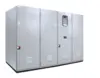
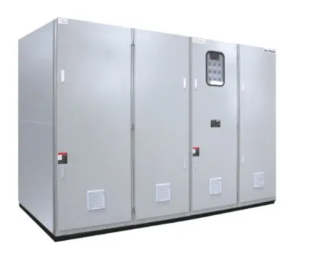
1. Overview The YDQ6 liquid resistance rotor starter (hereinafter referred to as the starter) is a new type of starter developed to improve the starting performance of large and medium-sized wound-rotor AC asynchronous motors. It overcomes the problems of high inrush current, difficult starting and inconvenient operation of frequency-sensitive resistor starters. It is suitable for heavy-load starting of motors such as ball mills, air compressors, crushers, large fans and large water pumps in industries such as building materials, metallurgy, chemical industry and mining. It is an ideal replacement for frequency-sensitive starters and metal resistance starters. 2. Standards and Specifications: GB/T 191 Pictorial Markings for Loading, Storage and Transportation; GB 4208-2008 Degrees of Protection Provided by Enclosures (IP Code); GB/T 5226.1-2008 Safety of Machinery – Electrical Equipment for Machinery – Part 1: General Technical Conditions; GB/T 13384-2008 General Technical Conditions for Packaging of Electromechanical Products; GB 14048.4-2010 Low-voltage Switchgear and Controlgear – Part 4-1: Contactors and Motor Starters – Electromechanical Contactors and Motor Starters (including Motor Protectors). 3. Normal Operating Conditions: Ambient temperature: Upper limit not exceeding 50℃, lower limit not lower than -5℃ (Note 1); Relative humidity: Not exceeding 85%; Altitude: Not exceeding 2000M (Note 2); Should be placed indoors in an environment free from severe vibration and impact, with a vertical tilt not exceeding 5°, and free from fire and explosion hazards; Conductive dust and corrosive gases are not permitted; Power supply: Three-phase four-wire 380/220V. 20A (Note 3), and voltage fluctuations must be guaranteed to be within ±15% of the rated voltage. Note 1: When the ambient temperature is consistently below 0℃, a heater needs to be installed; this should be specified by the user when ordering. Note 2: For altitudes exceeding 2000 meters, altitude correction should be made according to national standards. The correction factor formula is: H is the altitude, unit: meters. Selection should be made based on the altitude correction factor. Note 3: For power supply voltage levels that are special, this should be specified by the user when ordering; design can be customized according to user requirements. 4. Model Description 4.1 Meaning of Auxiliary Codes: K: For low-voltage motor primary circuit; B: For vacuum contactor used with short-circuit contactor; PC: For programmable logic controllers (PLCs). Auxiliary codes can be used in combination. Only the 0.4 series can be used with low-voltage motor primary circuits. Electric heating function is required when the ambient temperature is consistently below 0℃. PLCs can be selected as needed. 5. Product Features 5.1 Basic Principle This starter uses a mechanical transmission device to gradually reduce the distance between two parallel plates in a conductive liquid until it reaches zero. This causes the resistance value in the motor rotor circuit to gradually and smoothly decrease from its maximum to zero, allowing the motor speed to gradually and smoothly reach its rated speed. This achieves smooth heavy-load starting of wound-rotor large and medium-sized motors. 5.2 Technical Features 5.2.1 Low and constant starting current, with no impact on the power grid; the starting current is no more than 1.3 times the rated current, thus reducing the transformer capacity requirements for heavy-load motor starting and reducing initial investment. 5.2.2 Smooth starting reduces impact on mechanical equipment and extends the lifespan of both the equipment and the motor. 5.2.3 Large heat capacity, allowing for 2-5 consecutive starts. 5.2.4 Can start even at low voltage; as long as the power grid voltage can ensure normal motor operation, smooth starting is guaranteed. 5.2.5 Simple structure, convenient maintenance, and superior reliability compared to frequency-sensitive and oil-immersed rheostats. 5.3 Technical Parameter Table 1: Technical Parameter Table Model Compatible Motor Power (kW) Starting Time (S) Water Tank Capacity (L) YDQ6-0.4 ≤400 20~60 180 YDQ6-0.6 ≤600 280 YDQ6-1 ≤1000 320 YDQ6-2 ≤2000 540 YDQ6-3 ≤3000 880 YDQ6-4 ≤4000 1320 YDQ6-6 ≤6000 1680 YDQ6-7 ≤7000 2400 YDQ6-8 ≤8000 2760 YDQ6-10 ≤10000 4600 YDQ6-12 ≤12000 5100 Note: 1) The starter structure for larger capacity motors will be designed and manufactured separately according to user requirements. 5.4 Simple Calculation Method for Selection 5.4.1 Product Selection Data: Motor parameters, load type, ambient temperature, number of starts per day 5.4.2 Calculation of heat generated per start: Qq=3×0.24×Iq2×Rq×tq/2000(Kcal) Where: Qq is the heat generated per start; Iq is the starting current; Rq is the maximum liquid resistance of the starting series; tq is the starting time. 5.4.3 Load Classification: Light load: mills, roller presses, rolling mills, compressors, etc.; Heavy load: fans, crushers, etc. 5.4.4 Allowable Temperature Rise per Start (ΔT) Temperature rise per start (ΔT) = (Alarm temperature T1 - Cold start temperature T2) / Number of consecutive starts required (n) Where: Alarm temperature (usually 60℃) T1; Cold start temperature (ambient temperature) T2; Number of consecutive starts allowed n: 5.4.5 Water Tank Volume Calculation: M = Qq / (C0 * ΔT) Select the appropriate model based on the calculated water tank volume and the technical parameter table. 6 Structural Introduction This starter is a cabinet-type structure. The standard protection level is IP30, but can be IP55 for special requirements. The structural form can be configured according to user requirements. See the installation diagram, top view, and tables for the basic structural form and external dimensions. Table 2. External Dimensions, Installation Dimensions, and Equipment Weight Model | External Dimensions (mm) | Installation Dimensions (mm) | Weight of Water Added Before Solution Preparation | A | B | C | E | F | Φ | KG | KG YDQ6-0.4 | 740 | 860 | 2000 | 560 | 710 | 18 | 200 | 380 YDQ6-0.6 | 740 | 1060 | 2000 | 560 | 910 | 18 | 250 | 530 YDQ6-1 | 840 | 1060 | 2000 | 660 | 910 | 18 | 300 | 620 YDQ6-2 | 1040 | 1060 | 2000 | 860 | 910 | 18 | 400 | 940 YDQ6-3 | 1240 | 1260 | 2000 | 1060 | 1110 | 18 | 480 | 1360 YDQ6-4 1240 1460 2200 1060 1310 18 580 1900 YDQ6-6 1540 1460 2200 1440 1350 18 720 2400 YDQ6-7 2140 1660 2200 2040 1550 18 900 3300 For larger sizes, please contact us for consultation. 7 Installation 7.1 The starter should be installed on a drainage-accessible concrete platform. 7.2 The installation ground should be level, with a channel steel base (Figure 1). The horizontal plane error within 1000mm of the installation surface should be less than 1mm. The channel steel base should be 1-5mm higher than the ground. The cabinet should be installed perpendicular to the horizontal plane. 7.3 It can be installed using anchor holes or angle steel; either method is acceptable. 7.4 The cable enters from the bottom or back of the starter and connects to the copper busbar at the lower end of the shorting contactor. Secure the cable to the rear beam of the cabinet with cable clamps. 7.5 If a phase feeder is provided, the rotor cable should first go to the phase feeder, and then connect to the starter from the phase feeder. 7.6 The control power supply uses a 3×2.5+1×1.5mm² cable to enter from the bottom of the rear of the cabinet and connect to the terminal block. Connect the interlocking control lines between the liquid starter and the primary cabinet, DCS system, or other central control system according to the drawings. 7.7 Configure a green and yellow grounding wire at the grounding post. 8 Equipment Commissioning 8.1 Preparation of Liquid Resistor: 8.1.1 The resistor solvent is the water used for preparation, preferably distilled water or softened water, and at the very least, domestic water that has been left to stand to remove sediment. 8.1.2 The resistor solute is the resistor powder, provided by our company. 8.1.3 Determination of the liquid starting resistor Rq: Please contact us for details on the calculation formula. 8.1.4 Resistor Preparation 1) First, place the moving plate at the upper limit position and pour the prepared water into the water tank to about 2/3 of the specified position. Note that the liquid levels of the three phases should be basically equal. 2) Weigh a certain amount of electrolyte powder (refer to Appendix 1 for the amount of electrolyte powder to be weighed). 3) First, pour the prepared water into a container such as a basin or bucket. The water should not exceed 2/3 of the container's volume. Take 1/3 of the weighed electrolyte powder and slowly pour it into the container while stirring continuously until the electrolyte powder is completely dissolved. Then pour it into one phase of the resistance box. Dissolve any partially dissolved lumps with hot water. If there are still a small amount of insoluble matter, discard it. If there is too much electrolyte powder and the container volume is too small, dissolve it in several batches. 4) Repeat step 3) to dissolve the electrolyte powder into the other two phases. 5) Add water to the liquid resistance box to the required liquid level (the liquid level is about 60mm from the top cover of the resistance box). 6) Press the test button to move the plate up and down two or three times to stir the resistance liquid in the box evenly. 7) Wipe the water stains off the outside of the resistance box with a clean cloth. 8) To measure the liquid resistance, disconnect the motor rotor connection cable, move the movable plate of the liquid resistor to the starting position, and then pass a 50Hz current between the moving and stationary plates of each phase through the autotransformer. The current gradually increases from 0 to about 5A. Record the reading of the ammeter A and measure the voltage drop V between the two poles. For details on the calculation of the liquid resistance value, please contact us. 9) If the resistance is too high, the concentration of the resistance liquid should be increased; otherwise, the concentration should be decreased. The adjustment method is to use a soft tube to draw out part of the solution and add water or electrolytic powder. Precautions: (1) When measuring the resistance, the movable plate must be at the upper limit position, and the rotor circuit must be disconnected from the resistance box. (2) The resistance liquid should be stirred evenly before measurement. (3) The phase line and neutral line of the voltage regulator must not be reversed. 8.2 Check the connection between the control line and the rotor cable 8.2.1 Check the connection between the control line and the rotor cable. 8.2.2 Check if the liquid resistance rotor starter uses a separate three-phase four-wire power supply. 8.2.3 Refer to the drawings to check if the interlocking control lines between the liquid starter and the primary control cabinet, DCS system, or other central control systems are correctly wired. 8.2.4 Check if the rotor wire is connected to the copper busbar at the lower end of the short-circuit contactor connected to the liquid resistor (do not fix the rotor wire initially; fix it after the resistance is measured). 8.2.5 Before powering on, carefully check for any missing, incorrect, or loose connections. 8.3 Starter Operation Test 8.3.1 Manually rotate the starter to bring the moving plate to the middle of the upper and lower limits. After checking that the three-phase control power supply is normal, turn the "Work/Test" switch counterclockwise to the "Work" position and close the air switch inside the cabinet. If the moving plate moves upwards, the phase sequence is correct. 8.3.2 The moving plate should stop at the upper limit. If the moving plate moves downwards, the phase sequence is incorrect. In this case, turn off the power and swap the two phase power lines. 8.3.3 Turn on the power to the control and drive motor. If normal, the plate will perform a self-test (first moving downwards for about 2 seconds, then resetting to the upper limit). The "Allow Start" indicator light will illuminate. Turn the "Work/Test" switch clockwise to the "Test" position. The plate will move downwards, the "Allow Start" indicator light will turn off, the plate will stop at the lower limit position, and KM2 will engage. The "Run" light will illuminate, indicating that the equipment is operating normally. 8.3.4 Timeout Protection Setting (This time is factory-set and does not need to be set on-site). If the start time needs to be adjusted on-site, it needs to be readjusted. Setting method: Repeat step 8.3.3 and use a timer to measure the start time T from the upper limit position to the lower limit position. If the starter does not have a PLC, the protection time of the overtime protection relay needs to be set so that the overtime protection time is 3-5 seconds longer than the starting time T. If the starter has a PLC and the starting time has been adjusted on site, the overtime alarm action time in the PLC program needs to be adjusted so that the protection time is 3-5 seconds longer than the starting time. Note: If the control power supply needs to be changed for work purposes, please determine the phase sequence according to the above method. 8.4 Power-on test 8.4.1 Turn on the starter control power supply and perform the starter operation test again. If it is normal, turn the "Work/Test" switch to the "Work" position. 8.4.2 Simulated test 1) Set the main motor primary cabinet to the "Test" position and only turn on the control power supply of the primary cabinet and the starter. 2) When the starter's "Start Allowed" indicator light illuminates, press the primary cabinet closing button. At this time, the primary cabinet switch closes, and the starting plate begins to move from top to bottom. The "Start Allowed" light goes out. When it reaches the lower limit position, the short-circuit contactor KM2 engages, the "Run" light illuminates, and the plate automatically resets to the upper limit. This indicates that the starting and running are normal. 3) Press the primary cabinet opening button. The primary cabinet switch opens, KM2 disconnects, and the "Run" light goes out. If there is no fault, the "Start Allowed" light illuminates. This prepares for the next starting operation. 8.4.3 Starting Test 1) Turn on the primary circuit power supply and the control power supply for the primary cabinet and starter, and set the primary cabinet to the "Working" position. 2) Start the motor in the simulated test sequence and observe whether the starting current is within the specified range (1.1~1.3I1e). If the starting current is too high at the beginning, it indicates that the resistor is too small. In this case, the concentration of the resistive fluid should be reduced. The method is to draw some liquid from the water tank, add an equal amount of clean water, stir well, and then test the start again. If the starting current is too low at the beginning, and the impact is too large when the KM2 contactor closes, it indicates that the resistor is too large and should be reduced. In this case, the concentration of the resistive fluid should be increased. The method is to draw some liquid, add an appropriate amount of electrolytic powder (do not add too much at once), fully dissolve it, and pour it into the water tank. Adjust until the starting current is normal. 8.5 Common Faults and Handling (Table 3) Table 3 Fault Phenomenon Fault Cause Inspection and Handling Audible and Visual Alarm Low Liquid Level a) Check if the liquid level switch is malfunctioning. b) Add water to the initial position. Liquid temperature too high. a) Check the thermometer setting (approximately 75℃). b) Check if multiple consecutive starts caused the liquid temperature to be too high, triggering the circuit breaker. Timeout protection. a) Check the coil of the rotor short-circuit contactor. b) Check the auxiliary contacts of the rotor short-circuit contactor. Excessive current surge when switching to full speed. a) Check the lower stroke position; check if the moving plate has not reached the lower limit, resulting in excessive residual resistance. b) Check if the starting time meets the load starting requirements. If not, adjust the starting resistor to increase the starting torque or extend the starting time. 9 Use and Maintenance 9.1 Before starting the equipment, power must be supplied to the control cabinet. Start-up is only permitted when the "Start-Allowed" indicator light is on. 9.2 The electrolyte should generally be replaced every 4-5 years. Simultaneously, the plates and insulating housing should be cleaned. For plate cleaning, the conductive surface can be etched with dilute hydrochloric acid first, then rinsed with clean water. For insulating housing cleaning, first wash with clean water and let it dry, then apply epoxy resin several times (under normal circumstances, it is best not to disassemble for cleaning; if disassembly is necessary, avoid vibration and impact to prevent housing breakage). 10 Packaging, Transportation, Storage, and Unpacking Inspection 10.1 Packaging requirements: Users can choose simple packaging, domestic packaging, or export packaging requirements. 10.2 The resistor cabinet should not be moved lying down to avoid damage to the cabinet and insulating housing. The tilt angle during handling and storage should not exceed 15°. Special requirements should be discussed separately with the manufacturer. Use a forklift or crane to move the packaging boxes, avoiding impact during handling, and lifting should be carried out according to the storage and transportation markings. 10.3 Avoid direct sunlight and rain during storage. 10.4 Before unpacking, check whether the packaging is intact. If severely damaged, negotiate with the transportation company or contact our company. When unpacking and lifting the cabinet, hook it onto the lifting rings on the top of the cabinet. Lifting should be done using a 4-point hoisting method, ensuring even force distribution at all four points to prevent deformation due to uneven stress. 11. Ordering Information 11.1 Motor power, stator voltage, stator current, rotor voltage, rotor current; 11.2 Load type; 11.3 Number of starts per day; 11.4 Cabinet color (as per company standard or special specifications); 11.5 Short-circuit contactor or circuit breaker (as per company standard or specific specifications).
- Soft starter
- liquid resistor
- water resistor
- variable resistor
- LRS
Production Capacity:
2000
Delivery Timeframe:
Within 30 Days
Incoterms:
CFR - Cost and Freight
CIF - Cost, Insurance and Freight
FCA - Free Carrier
FOB - Free on Board
Packaging Details:
海运木包装或加强包装
More about
Big Pawer Electrical Technology Xiangyang Inc. Co., Ltd.
200-500
Employees
10M - 50M
Sales volume (USD)
10%
% Export sales
Year
Established
Business type
- Industry / Manufacturer
Keywords
- Soft starter
- frequency converter
- variable frequency speed control
- motor control
- switch cabinet
- control cabinet Ver Mais
Contact and location
-
 WJ ********
-
+86 8********
-
Xiangyang / Hubei | China
